Sunday, June 15, 2014

Fixing Ravensburger Tiptoi

Thanks to my college from work I had a chance to look at apparently popular toy called tiptoy. Basically it is a RFID infrared camera combined with a mp3 player. There are books with embedded RFID tags small points printed over the regular pictures. Those points are almost invisible to a human but tiptoy recognizes them and plays back some records when its tip touches tags in a book so a child gets interactive description of what is in the book. Different images or areas of images have different points pattern.
A typical problem of the tiptoy is that its speaker is not completely child proof and after some time the toy becomes mute. This particular toy worked with a headphones normal so my friend decided to try changing a speaker what solved his problem. Here come some pictures he took:

 Take batteries out, unscrew four screws.

 Take speaker out and desolder it.
Both speakers - the original one and the new not installed yet one.
This is close-up how the speaker is mounted.
You can ensure that the speaker caused a problem by measuring its resistance.
This is measured resistance of the new speaker, close to 8 Ohms is correct.

This is resistance of the damaged speaker. 2.3MOhms is almost open circuit - a speaker is damaged.

Tuesday, May 13, 2014

Brushless motor from RC model as a CNC spindle - 3D printed

I do have a small CNC milling machine at home, I build to be able to prepare housings for my electronics projects. The machine has a working area of around 200x300x70mm and a typical 43mm tool holder. A spindle which I used at the beginning was 550W Kress FM 6955 without any speed regulation. I tried to supply it from phase controller but stable regulation range was just to narrow. Kress is a great tool but is extremely loud, I was thinking about building something smaller what would fit 43mm holder to be able to change tool quickly.
I don't expect it to be fast and powerful, the main criteria is to have a quiet machine to be able to work at home. 
At the same time my great college from work got himself a Prusa 3D printer, I see he has got a lot of enthusiasm for printing and is happy to challenge his machine so I designed in a Freecad two holders for 608 bearings around which I build my tiny CNC spindle. Following pictures show the designing process.
This are screenshots from a FreeCAD:
And this are two holders as came from 3D printer. Note square nuts which are faced with a surface of "ears".
This is ER8 collet with a 8x100 roller and one 608 bearing already pressed on.
The construction is hold by three pieces of M4 screw threads, there is a brushless RC motor attached to the round aluminium plate which serves a s heatsink for the motor too.
I don't have access to lathe so I had to improvise a coupling out of a piece of elastic hose which is supposed to be a fuel hose in a garden lawnmower. I can recommend this type of hoses because of their incredible flexibility. Soon I will be able to tell how does it withstand higher temperatures because the motor is heating significantly. 

Pros:
-the construction is much quieter than the "big" spindle and is strong enough to mile with 1x4mm bit in a plywood
-scaleability - you can easily mount a bigger and/or different motor
-easy accessible parts - ER8 collet costs around 10 Euro if ordered from China (ebay), motor around 20 plus 10 for ESC to drive it, rest of components is maybe another 10 Euros and can be obtained in a regular hardware store, usually DIY people have some sort of power supply so I will not put it on a bill.

Cons:
-bearing is getting warm when rotating, I didn't do long run tests but I have some concerns, BLA - material used for 3D printed parts has got a glass transition temperature of around 65 oC so there is not much headroom without forced cooling. Another possibility is to search bearing with a lower friction, I will update this page as soon I will get any test results.


Sunday, May 11, 2014

Opel Astra H sport button

In my Astra H there is a button which controls a park assist radar, some other versions of Astra H have a "sport" button there which changes a gas pedal, suspension (if car is equipped with IDS) and traction control settings.
I wanted to change the middle console module for a one with a "sport" button but I couldn't find any information if the middle console module in both variants (with parking radar and with "sport") has the same circuit - is this only a matter of a sign on a button and activating the right option in cars ECU or it is needed to change button module to be able to activate "sport" button?
I bought a middle module with "sport" and did a short investigation, here is the disassembled module:

Here is connector with pin numbers which I assumed:
And here is a reverse-engineered circuit diagram:
Safety related features in a car have additional diagnostics. Sport button is safety related because of influence on cars traction and for this reason there is additional 1k resistor across the switch so ECU can detect if the button connected correctly. If button is missing then most probably ECU will switch off this potentially dangerous sport mode. Door lock button and hazard lights can't directly cause a harm and they don't have this additional 1k resistor.
I didn't took the regular module without sport button yet but I will put here a circuit diagram and circuit comparison when I do this.

Wednesday, February 5, 2014

Fixing Voltcraft 8202 sweep/function generator

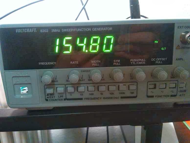
Recently I ordered from ebay a defected Voltcraft 8202 function generator. It powered up properly and showed on the display a frequency. It wasn't completely damaged but there was no output signal, no matter what amplitude and offset I set there was 0 Volts on the output.
I assumed that the problem is somewhere in output stage, this sound like a typical damage for a signal generator which once had its output overloaded. After opening the generator up I traced signal backwards from output connector, circuit diagram of output AB-class amplifier area looks like this:
This is actually really popular topology, signal (point A) is fed to the positive input of the differential amplifier built around Q12 and Q13, Q14 drives Q15 and Q16 push-pull output stage while D6 and D7 provides bias voltage for Q15 and Q16. Signal from the point between R59 and R60 is fed back to negative input of Q12 and Q13 amplifier - this negative feedback improves linearity. Between point B and the output BNC connector there is additional switchable 20dB voltage divider which I didn't show on the circuit.

Multimeter set to a diode test showed that Q14 was damaged, additionally R59 and R60 were overheated, one of them was opened, another looked bad but was still conducting. R57 in the negative feedback has drifted because of overload and was around 30K instead of 6.8K. I replaced Q14 with BC557, put new R59, R60 and R57 but there still was no output signal.

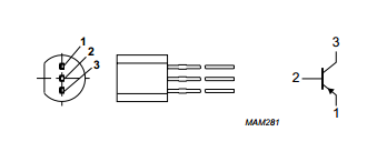
It took me a while to notice that the original 2N3906 has got different pinout than the BC557 which I used, actually pin numbers are the same: emitter is the pin number 1 but take a look at this screenshots from datasheets:
2N3906

BC557
The order in which pins are numbered is different. After rotating the BC557 generator started to work again. I enjoyed watching sinusoidal and triangle signals on a screen of my oscilloscope. I didn't enjoyed watching square waves because their edges are really slow, slew rate of around 1V/us. It looks acceptable at 100kHz, but at 1MHz it is not a square wave anymore.
Another observation is about PCB quality, it was enough to solder one point twice to tear copper of the PCB:

I don't mind because not very often I look at this PCB but it says something about overall product quality.

Sunday, January 26, 2014

Fixing Fender Hot Rod Deluxe PR-246 (solder cracking)


Fender Hot Rod Delux is a 40 Watt hybrid guitar amplifier. This particular one had a problem of a cracking noise. There was a normal sound coming out of the speaker but with annoying full volume cracks, while playing cracks happened more often then in a standstill. 
The owner told me that he wanted to by a new set of vacuum tubes because he noticed that he can cause this disturbance by touching the left most 12AX7A tube. I took a look at the tube and noticed that it is quite difficult to take it out because tube sockets are fitted very tight.
After opening a back of the implement I took a look at a PCB and noticed that there actually was a solder crack on the pin of tube socket. The crack is visible in the center of this picture:

I heated this broken solder joint with soldering iron, added some new solder and problem was fixed. As a precaution I reworked the same way all pins of this tube socket because if one solder joint was broken than another one was just waiting to crack.
Lesson learned:
1. Be careful with replacing tubes - they are fragile and rest of an amplifier is too.
2. PCB holes diameter for this tube socket are in my opinion a little bit to big giving pins possibility to cause mechanical tension while replacing tubes. Sockets have no mechanical support except for solder joints - shame on you Leo Fender!

Wednesday, January 8, 2014

Fixing Honeywell Rondostat


In a scrap parts box I found a Honeywell Rondostat - a radiator thermostats which allow you to define different time zones and different temperatures for them, it is even aware of a day of a week and can control temperature accordingly. The thermostat I found was where it was for a reason, actually two: after putting batteries it turned out that a metal spring which connects batteries in series is loose and doesn't provide right electrical contact. This shiny metal part here:
It was a bit tricky to get it out:
But it was possible without demolishing whole device:
I bent this metal part so it was a bit tighter put it back, plugged two AA batteries inside and the Rondostat started to work immediately. New problem was that a adaptation process in which the thermostat learns what is possible valve operation range ended with an error. As it turned out it was a problem with a built-in gear. I pulled out the gear by levering three snaps, for two snaps I used stripes of EC card which I sicked into holes which are actually there for detaching gear:
 Third snap is under control PCB which is easier accessible:
Root-cause of the gear adaptation problem was this little gear - metal axle was pushed into plastic part too deep:
With a pair of tweezers I pulled the axle out and put it back in but not that deep like it was before. Last step was to assembly it all back together. If you try it on your own, be aware that the gear with two metal parts has to be placed on top. This metal parts make gear visible for rotation sensor on PCB.

 Further steps for putting it back are fairly easy and Rondostat works now.
This is PCB with NEC microcontroller, red connector is for a DC motor connected to the gear.

Honeywell Rondostat doesn't look like a new one, from a layer of dust I suspect it is more than one year old but mechanics is still OK. I didn't see any wear-out, it makes reliable impression. One problem with axle moving into plastic part might be planned obsolescence but even if - It is comparatively easy to fix it. I know that this thermostat was in a scrap box more than two days and surprisingly its clock was almost correct, turns out to have some super-cap or battery backed up RTC.
Last point is that I suppose that Rondostat does not like rechargeable batteries because of their lower voltage, I will try to test it deeper maybe my rechargeable batteries were already flat.