
This is actually really popular topology, signal (point A) is fed to the positive input of the differential amplifier built around Q12 and Q13, Q14 drives Q15 and Q16 push-pull output stage while D6 and D7 provides bias voltage for Q15 and Q16. Signal from the point between R59 and R60 is fed back to negative input of Q12 and Q13 amplifier - this negative feedback improves linearity. Between point B and the output BNC connector there is additional switchable 20dB voltage divider which I didn't show on the circuit.
Multimeter set to a diode test showed that Q14 was damaged, additionally R59 and R60 were overheated, one of them was opened, another looked bad but was still conducting. R57 in the negative feedback has drifted because of overload and was around 30K instead of 6.8K. I replaced Q14 with BC557, put new R59, R60 and R57 but there still was no output signal.
It took me a while to notice that the original 2N3906 has got different pinout than the BC557 which I used, actually pin numbers are the same: emitter is the pin number 1 but take a look at this screenshots from datasheets:
 |
| 2N3906 |
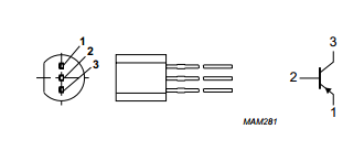 |
| BC557 |
Another observation is about PCB quality, it was enough to solder one point twice to tear copper of the PCB:

I don't mind because not very often I look at this PCB but it says something about overall product quality.