1. visualy inspect VCC and GND rails on the PCB
2. use Ohm's law
Visual inspection might be not so easy, have you heard about tin whiskers? http://www.eetimes.com/electronics-news/4234309/Toyota-accelerations-revisited-hanging-by-a--tin--whisker visual inspection is hard and not cool. I decided to use mighty Ohm's law. Presented circuit was designed to by supplied from 5V and all components were already placed so we had to bear in mind that voltage. I set desktop power supply for 5V, current limit for 3A and connected to PCB. Current limit worked and voltage measured across GND and VCC rails was about 0.3V - circuit was shorted.


Measured voltage increased so I knew that current flowed through part C of track. Repeating that procedure I found drop of tin at the left-most end of track C. That's easy: you are moving one tip of a multimeter and measure voltage across track, if voltage increases - that means that tip of a probe is getting closer to short circuit point. This method is easily extendable and can be used in much more complicated PCBs. I never found it in a handbook so I decided to desribe it and share here. Hope it will help you one day.
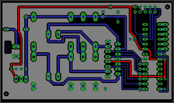
Here is real
view of a mentioned PCB:

No comments:
Post a Comment