Friday, September 21, 2012

DRLv2 light controller

What does it actually do?


It constantly measures the car battery voltage and based on the voltage level it knows if the engine is running or not. When engine is running it switches DRL lights on. Depending on the selected operation mode it simply switches DRLs on and off  or it dims up and down. It also monitors state of low-beam light and turn indicator to perform some other nice things.

When engine is switched on (car battery voltage is above 13.5V):
-switches DRL off when it detects that low-beam lights are on
-switched DRL on when it detectd that low-beam lights are off so car battery will last for a longer time if you left it for a while.

When engine is switched off (car battery voltage is below 13.0V):
-switches DRL on for a 30 seconds when it detects that car have been just locked or unlocked. It simply detects one or couple of blinks which are usually emitted when you lock or unlock your car with remote controller. This function is something like “follow me home” lights, DRLs consume so little power that it's not a problem to switch them on for such a short time.
-when DRLs are already on and circuit will detect that car has been again locked or unlocked it will switch DRLs off. So you can use your remote to switch DRLs on and off when your car is parked

-detects emergency lights being switched on – in such case it will ignore blinking turn signals and will keep DRL lights off.

Car battery monitoring serves as protection against deep discharge in case of alternator failure. It also switches DRLs on after the engine has started. It doesn't consume power at that exact moment when engine starter works so it eases start-up.

Whole circuit in stand-by consumes less than 1.5mA, it would take about 2 years to discharge a typical car battery with this current. It is protected against wrong polarity and thanks to fuse it is protected against DRL short circuit. It can control DRLs up to 30Wats, witch in case of LED DRLs is far enough.  


Why did I build it?
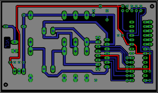
My car wasn't factory fitted with day running lights. In my country it is legal obligation to always drive with day running lights or with low-beam lights on. I once calculated that low-beam lights which consume more that 110Wats increase fuel consumption by around 0.25 l/100km (approximately 1,5 mpg US). I can prove it using a pencil and a sheet of paper. LED DRL consumes about 10Wats. According to EU law DRL lights should be automatically switched on when engine is started and they also should by switched off when low-beam lights are switched on. This automation is usually done by a simple relay connected to low-beam light and a wire which is connected to +12V simultaneously with turning on ignition. Using relay, although it's simple, has got disadvantages. Typical relay-based controller unnecessary drains car battery when engine is starting, it also needs to be connected to wire which is connected to battery positive terminal simultaneously with ignition. In my car it is not so easy access such a wire. I noticed that cars battery is quite easy accessible and project has started. I draw a simple circuit mentioned in one of my previous posts, I designed PCB keeping in mind that it have to fit to a typical plastic housing and ordered handful of necessary components.

After two weeks of impatient waiting I finally received 12 brand new PCBs for my Day Runnig Light controller. They fit to plastic housing which I had bought earlier. Looks like they will be ready for testing in a next week.

I have mounted 4 pieces so far – that's enough for development purposes:


PCBs are sealed with epoxy to make sure that they will survive dust, moisture and wide range of temperatures. On the picture below I marked pin order.

How to connect it?

Connections which you have to make are marked with colors, connections which are already in your car are marked with black.

Sometimes there are issues with particular DRL lights which don't like dimming, this controller can work in two modes: with or without dimming. When it works without dimming it does exactly the same thing but it adds some extra delays instead of dimm-up and dimm-down periods. There is no switch to choose whether it does dimming or not. Instead of some potentially unreliable switch it uses tricky technique: it learns which input is connected to low-beam light.
If low-beam light is on INPUT1 (and consequently turn indicator on INPUT2) DRLv2 works with dimming. If you swap it and connect low-beam light to INPUT2 it will work without dimming.
Controller learns on which input there are short pulses (turn indicator) and on which there is constant positive state (low-beam). After installing controller into your car you should switch low-beam lights for let's say 5 seconds or longer so it can learn that this is low-beam input and choose desired mode.


Thursday, September 20, 2012

Digital camera remote control


One of my friends wanted a microcontroller to send commands to a digital camera. There are lots of such projects on the web and there is even more cheap Chinese remote controllers but no remote does exactly what my buddy needed. He already had a hardware which I mentioned in previous post and a regular remote controller for his Olympus camera. First of all we had to generate 36KHz carrier frequency, we did it using Timer1 in CTC mode:

PORTB &= ~(1<<1);   //there is 0 on pin when OC1A is disabled
DDRB   |= (1<<1);   //OC1A pin works as output
TCCR1B |= (1<<WGM12) | (1<<CS10); //CTC mode and clock source selection
TCNT1 = 0;   //clear timer register
OCR1A = 14;   //1MHz/(2*36KHz) ~ 14
//TCCR1A |= (1<<COM1A0);   //enables OC1A output

Then we had to key carrier frequency with data which will convince camera to take a picture. Information sources we used were lirc drivers www.lirc.org and signals received from regular controller. Every bit consists from two consecutive states zero and one, meaning of a bit is encoded in length of the second state. This way transmission is immune against clock desynchronization. Data transmitted by remote controller which we reverse-engineered looks like this:  
It turned out that camera needs only that marked with red box part of a signal. Rest of transmission is redundant in case of that specific camera. Setting and clearing COMA10 bit controls whether carrier frequency is supplied to IR LED or not, we wrote simple preprocessor directives:

#define HEADER TCCR1A |= (1 << COM1A0); _delay_us(8853); TCCR1A &= ~(1 << COM1A0); _delay_us(4489);
#define ONE TCCR1A |= (1 << COM1A0); _delay_us(559); TCCR1A &= ~(1 << COM1A0); _delay_us(1670);
#define ZERO TCCR1A |= (1 << COM1A0); _delay_us(559); TCCR1A &= ~(1 << COM1A0);  _delay_us(555);  

And function sends a “take a picture” command to camera:

HEADER;
ZERO;ONE;ONE;ZERO;ZERO;ZERO;ZERO;ONE;ONE;ONE;ZERO;ONE;ONE;ONE;ZERO;ZERO;ONE;ZERO;ZERO;ZERO;ZERO;ZERO;ZERO;ZERO;ZERO;ONE;ONE;ONE;ONE;ONE;ONE;ONE;ONE;

Now when we knew that it works we'll clean up this code to make it non-blocking, neat and easy to read and maintain. The most important thing is that controlling digital camera is not_so_difficult_as_you_thought.  


Wednesday, September 12, 2012

Lambda sensor based Air-fuel ratio indicator [AFR] 1

Once I bought a new car with a fuel injection I started to think how to improve my fuel efficiency. I know that engine breaking is efficient, I also sometimes tried to explain this technic to my mates. To help myself I designed little circuit which "steals" voltage from lambda sensor and uses two-color LED to show you if drive efficiently or not. (to show if engine runs on lean, stoichiometric or rich mixture)


What does it do?
When you drive in a steady conditions, engine warm, no strong acceleration engine computer controls amount of fuel to produce clean exhaust, this can be observed on voltage from lambda sensor as values ranging from 200mV to 800mV

In such case this circuit will light both colors of LED producing yellow light as a information for driver that everything is normal, AFR is close o to 1.
When you do engine braking - it means release gas pedal engine computer will stop fuel flow - engine does not consume fuel, it can be observed as voltage from lambda sensor close to 0V. Presented circuit will light up green LED to show you how clean and cheap you driving is at that moment.
Right after turning on cold engine and when you try to accelerate quick engine computer will let some extra fuel to pistons - your car consumes much more fuel than in cruising conditions. This device will light up red LED to warn you that you should expect huge fuel consumption.


How does it work?
Lambda sensor is connected to engine controll unit like this:
Signal from this sensor informs engine controll unit about mixture richness, I decided to measure this signal like this:

I did some measurements with my good old Tektronix scope just to makse sure that theory of lamba sensor applies to my car and than I draw something like this:
On the left side is a main connector, two terminals are connected to lambda sensor and other two to +12V and to ground. Signal from lambda sensor is fed to differential amplifier IC3A. This might seem to be not necesary because most of lambda sensors have got grounded terminal. But I wasn't certain if my ECU does it. I also didn't want to damage ECU or sensor when I tinker with this vital signal in my car so I used differential amplifier as separation stage. +12V is regulated by good old-fashined 78L05 to supply microcontroler. I used PIC12F510, mostly because of its low price. Two colour LED is conntroled by microcontroller.

How to build one?
I draw a small one-sided printed circuit board for all components, this is a result:
minimalistic, isn't it?


Tuesday, September 11, 2012

How to find a short circuit on your PCB

My friend has fabricated PCB for his stepper motor controler. He etched and soldered that board at home but due to lack of soldermask there was short circuit between VCC rail and ground. We knew for sure that there was no short circuit in a design so it had to be a drop of solder in a wrong place. We could do two things:
1. visualy inspect VCC and GND rails on the PCB
2. use Ohm's law
Visual inspection might be not so easy, have you heard about tin whiskers? http://www.eetimes.com/electronics-news/4234309/Toyota-accelerations-revisited-hanging-by-a--tin--whisker visual inspection is hard and not cool. I decided to use mighty Ohm's law. Presented circuit was designed to by supplied from 5V and all components were already placed so we had to bear in mind that voltage. I set desktop power supply for 5V, current limit for 3A and connected to PCB. Current limit worked and voltage measured across GND and VCC rails was about 0.3V - circuit was shorted.
I marked VCC with red and GND with grey. Short circuit was somwhere between this marked rails. I connected PCB to the power supply like this:
Before I started to measure voltage across PCB tracks I did simple calculation just to know what voltage to expect. I knew that copper on the PCB was 35um thick and that VCC track widht was about 1mm. 1A flowing throug such track should cause voltage drop according to resistance of track. In this case 15mV/cm so values which are easily measured even with cheap chinese multimeter. First I connected multimere like this:

Measured value was close to zero so I came to conclusion that current is not flowing throug track A. I connected multimeter like this:
Measured voltage of 0.075V indicated that 3A short circuit current flows through track B. I moved a tip of multimeter further:

Measured voltage increased so I knew that current flowed through part C of track. Repeating that procedure I found drop of tin at the left-most end of track C. That's easy: you are moving one tip of a multimeter and measure voltage across track, if voltage increases - that means that tip of a probe is getting closer to short circuit point. This method is easily extendable and can be used in much more complicated PCBs. I never found it in a handbook so I decided to desribe it and share here. Hope it will help you one day.


Here is real view of a mentioned PCB:

Friday, September 7, 2012

GSM module power supply testing

Most GSM modules that I know need supply voltage in range 3.4 to 4.5[V] with voltage ripples less than 400[mV]. The main issue in designing such a power supply is that it has to maintain correct voltage even during voice call and data transmission. Not going into details current consumption during transmission looks like this:
So you see that surge current pulse takes 577[us] and is followed by about 4 [ms] of "pause". Burst current can reach 2A. I encountered problem with supplying GSM modules couple of times, sometimes clues you get from GSM module which is weakly supplied are really strange, for example Q2687 from Sierra Wireless won't reset when voltage is to low but it won't register to network, either.  Not to make that mistake again I decided to design a tiny little circuit to test voltage regulators designed for GSM modules.
It is as simple as possible - voltage from tested power supply is connected to X1-2 (+) and X1-1 (ground). Q1 MOSFET keys current which depends on supply voltage and value of R1. R1 is big, wire-wound resistor with power rating of 5W. Assuming that circuit is supplied from 4V and not taking into consideration resistance of opened MOSFET surge current should be about 2[A], when Q1 is switched off whole circuit consumes less than 1[mA] to power up PIC microcontroller. D1 diode prevents C1 from draining through R1, thanks to this diode and C1 microcontroller should work even during huge voltage dropouts across X1 terminals. I also added LED1 just to show that circuit is still up and running. You could also use GSM module to generate such distinct power consumption pattern but to do so you have to force module start GPRS session or to make voice call which seems to be impractical, I preffer to have such circuit so I can see both current and voltage on my ocillocope, analize voltage regulator response and do long-term tests under such load.
PCB project looks like this:


and as you can see - it is designed using only one signal side, that way I can make this PCB at home using well knonw method presented here http://www.riccibitti.com/pcb/pcb.htm


Channel 1 below is current measured with a 0.1Ohm resistor and channel 2 is voltage supplied to the real GSM module. Chanel 2 (voltage) had to be inverted because my oscilloscope doesn't have galvanically separated channels. It's easy o calculate that peak power consumption reaches 8W, when we consider low duty cycle average power is less than 2W but duration of peak is rather long - 595us, it's not that easy to store that amount of energy in filtering capacitors .


Wednesday, September 5, 2012

Światło rowerowe 1

W oczekiwaniu na nową wersję płyty drukowanej do DRL postanowiłem zacząć nowy lekki temat - lampkę rowerową tylną. Lampka ma mieć następujące funkcje:

  • Ładowanie kabelkiem micro-USB, w środku lampki jest bateria Li-Ion, jeżeli dopasuję obudowę to będzie to bateria BL-5C tania lubiana i znana z produktów firmy NOKIA
  • Przetwornica step-up do zasilania kilku LED'ów, ze względu na odprowadzenie ciepła zdecydowałem się na więcej LEDów o mniejszej mocy niż na jednego potwornie mocnego LEDa, plan jest taki żeby korzystając z not aplikacyjnych microchipa zrobić przetwornicę na bazie mikrokontrolera bez dedykowanego sterownika http://ww1.microchip.com/downloads/en/appnotes/01047a.pdf
  • Sygnalizacja dźwiękowa - przetwornik piezzo będzie informował o włączeniu, wyłączeniu i o rozładowaniu baterii. 
  • Touch-sensor zamiast włącznika mechanicznego - dzięki braku elementów mechanicznych ma być taniej i co ważne - szczelnie, hermetycznie szczelnie (czy to nie kłóci się z wystawienie gniazdka do ładowania?)

UWAGA UWAGA a teraz gwóźdź programu: czujnik przyśpieszenia:

  • automatyczne włączanie lampki kiedy rower rusza
  • automatyczne gaszenie lampki jak już zostawisz rower pod sklepem (oczywiście poprzedzone ostrzegawczym piknięciem, nie chcemy gasić lampki kiedy rowerzysta stoi we Wrocławiu w śluzie rowerowej na placu Bema). Po wykryciu bezruchu lampka sygnalizuje zamiar wyłączenia się kilka razy, jeżeli dalej trwa bezruch - lampka rowerowa gaśnie, jeżeli rowerzysta nie chce gasić lampki to wystarczy że poruszy rowerem żeby przerwać procedurę wyłączania
  • światło stop - kiedy sensor wykryje hamowanie - zwiększona zostanie jasność, może to jest bajer a może praktycznie przydatna rzecz? zobaczymy, zaprzyjaźniony rowerzysta mówi że w ciasnym peletonie rzecz może być przydatna o ile czas reakcji będzie wystarczająco krótki

Lampka ma być ultra widoczna - przewidywana moc zastosowanych LEDów to 1...2W co przy świetle czerwonym może dać mocny rezultat. Projekt w sam raz na jesień, jeżeli masz jakieś opinie na temat funkcji projektu to pisz, każdy pomysł jest dobry i pomaga mi zaprojektować praktyczny produkt.

Target cenowy - byłoby super gdyby lampka kosztowała około 50zł. Najdroższe elementy to: mikrokontroler, sensor MEMS, diody LED, tranzystor i cewka do przetwornicy, PCB i obudowa.