
Sunday, May 10, 2015
Voltcraft VC840 RS232 interface circuit
Q0 is a photo-transistor which receives IR light from a multimeter. If Q0 is illuminated then current flows through R1 and turns Q1 and Q2 on and the output R will be pulled down to positive voltage, this means mark will be transmitted. If Q0 is not illuminated then there will be negative voltage at the output R so space will be transmitted.


Monday, February 16, 2015
NTC temperature sensor connected over microphone input
Simple measurement
The idea is to measure resistance by connecting it to smartphone, to the microphone port to be precise. The simplest implementation would be something like this:

R1 and R2 form a voltage divider which dumps a signal from headphone output while microphone input records and measures amplitude. If one of resistors is known then second value can be found by comparing known headphone output amplitude with that recorded on a microphone input. C1 and C2 are capacitors which are always at the output and the input of a sound card. C1 is cutting off DC component so, without C1 there would be constant current flow through a headphones, even when playing back silence. The unnamed resistor to VCC is providing DC supply current for a microphone, C2 is not letting this DC current flow into ADC converter.
However
This circuit has got a huge disadvantage: it requires calibration with every smartphone you would like to connect it to. Additionally, I am not sure if headphone output doesn't change it's amplitude with temperature. Calibration seems to be not elegant solution so I though of using both headphone outputs and conducting a ratiometric measurement. Assuming that both headphone channels (left and right) provide the same amplitude if driven with the same signal, the influence of absolute amplitude could be eliminated from the equation.
Ratiometric measurement
||here will be a circuit diagram||
In this circuit there are two voltage dividers, R1 and R2 is dumping a signal from a left channel while R3 and R4 from a right channel. Microphone input measures sum of both divided voltages. Measurement is conducted by driving the left channel with a sinus signal, recording input amplitude, turning left channel off while the right on, recording input amplitude and doing calculations on recorded amplitudes.
Three of four resistors are known, the fourth is measured. To simplify calculations it is assumed that R2 and R4 resistors are the same while R1 and R3 are reference resistance and measured resistance.
to be continued...
.

Stimulus signal
For some measurement I needed a specially prepared .wav file with sinus wave interleaving between right and left channel. Octave manage to prepare that file but can't manage playback under windows 7 so I will have to use Audacity...
bps = 16; % bits per sample
sps = 48000; % sample rate [samples/s]
freq = 1000; % frequency of the tone [Hz]
nsecs = 2; % number of seconds of the audio file
interleaving = 1; % duration of "pack" on a channel [s]
nsamples = sps*nsecs;
interleavingSamplesNum = interleaving * sps;
time = linspace(0, nsecs, nsamples);
wave = sin(time*2*pi*freq)';
window1 = repmat([ones(1,interleavingSamplesNum), zeros(1,interleavingSamplesNum)],1,(nsamples/(2*interleavingSamplesNum)));
window1 = window1';
window2 = repmat([zeros(1,interleavingSamplesNum), ones(1,interleavingSamplesNum)],1,(nsamples/(2*interleavingSamplesNum)));
window2 = window2';
wavwrite([wave.*window1, wave.*window2], sps, bps, 'stimulus.wav')
temperatures=[];
for i=1:10
%playback prepared file and record microphone input simultaneously
i
system("play.exe stimulus.wav -t waveaudio", [], "async");
recordCommand=sprintf("SoundRecorder.exe /FILE recorded%d.wav /DURATION 0000:00:02",i);
system(recordCommand);
recordedFilename=sprintf("recorded%d.wav",i);
%recordedFilename=sprintf("recorded.wav");
y=wavread(recordedFilename);
deleteComand=sprintf("del recorded%d.wav", i);
system(deleteComand);
a=(sum(y(20000:30000).^2)/(30000-20000))^(1/2);
b=(sum(y(60000:70000).^2)/(70000-60000))^(1/2);
ratioResults=a/b;
resistanceNTC=ratioResults*10000;
temperature=ntc(resistanceNTC)-273;
temperatures=[temperatures, temperature];
%ratioResults=[ratioResults a/b]
endfor
I'd like to measure resistance value in circuit:

Of course, there is many limitations like AC coupling of mic input which forms actually a high pass filter, limited amplitude of microphone input signal, asymmetry between channels, clever estimating parameters of recorded sinus wave... but, let's give it a try. This is my prototype, four resistor can be put into DIL socket to ease changing values. One jack connector is for microphone input, another for headphones stereo output.

The measurement 1
I set up the prototype with following values
R2=R4=1k
R1=10k
R3=22k
Connected my oscilloscope to find out that the cheap Chinese USB audio card:


is actually providing around 2.23V DC into headphones output. This fact is not a problem for my measurement but can damage headphones. Anyway, here comes a waveform recorded by microphone input. The envelope of "packs" of sinus is surprising. I will do some further measurements to understand if DAC is not giving constant output or if microphone input is so bad quality. Probably these are some transitions because of microphone input capacitor. Next step will be to analyse recorded values to see if measured amplitude corresponds to expected amplitude...

Signal recorded by microphone input when stimulus signal has been played back.

Temperature logged in my room overnight. Celsius degrees, x axis are samples, not seconds.
Friday, February 6, 2015
Bicycle speedometer using hub dynamo to supply and as a speed signal
Idea
So I got one of this cool hub dynamos. I really like that it's quiet and efficient way of generating energy for bicycle lamps. I considered adding USB charger to my bicycle to be able to supply my mobile phone while cycling but this is not trivial topic because of low output frequencies from dynamo. Another problem is relatively low output voltage, 6V is to low to use LDO reliable, under low speed condition output voltage may be lower than 5V so eventually a step-up step-down converter would be useful. Additionally rectifying low voltages is kind of tricky, I mean you can do this easily but to do this efficiently is already a challenge because of immanent power loses in diodes (0.7V drop at 6 V input is already more than 10% loss).
As a byproduct of such consideration I drawn a simple circuit which uses LCD display and tiny micro to track frequency, which is directly proportional to the bicycle speed. I like the idea of using dynamo output voltage as a supply and a signal at the same time. You will never need to replace battery, and you don't need additional sensor on the wheel.
Circuit description

The speedometer is supplied from a hub dynamo. D1, C7 and C8 form a half-wave rectifier. C4 is ESD protection and D2 is a Zener diode which should be short-term overvoltage protection. IC1 is an LDO voltage regulator, carfuly chosen to have low quiescent current, C5 is output capacitor of the voltage regulator. Hub dynamo produces pseud-sinusoid signal with a frequency which rises with speed. At low speeds at big wheels frequency can go as low as 5Hz, and C7 and C8 have to store energy for the device.

Input waveform when supplied from signal generator.

Signal at SPEED node. Voltage limited to the value safe for microcontroler digital input. Not very "digital" but thanks to microcontrolers Schmitt input it's not a problem. Circuit supplied from signal generator.
 Waveform shows signal at SPEED node. Circuit supplied from a real hub dynamo (Shimano DH-3N31-NT).
Measurement
Because of required low power consumption micro has to run with 32[kHz] clock. The micro is actually measuring period, not frequency so division is needed. Fixed point arithmetic is used with assumptions that the speedometer shows integer part of the speed with proper rounding up and precision not worse than 0.1[km/h].

(verification of fixed point arithmetic)
Prototype

First prototype supplied from signal generator

First prototype supplied from a real hub dynamo driven by a DC motor
Software
Currently there is a github repository where you can download software and compiled.hex file. However this software doesn't show speed yet. It shows period in milliseconds before rising edges on SPEED signal. Stay tuned, new revisions are coming.
PCB
I designed a simple one-sided PCB using Cadsoft Eagle. Designing PCB with one layer only (the red top layer are wire connections which will be soldered manually) required changing association between mirocontroler pins and LCD segments. This is "layout friendly" now, software will have to compensate for this. Eagle files and gerber production files are packed along with software and can be obtained from github repository.


Todos
Add buttons
Add possibility to set up wheel circumference
Add captive touch sensor instead of mechanic switches
Add LED to back light the display while driving
Print a housing
Find a neat way of connecting the speedometer to the bicycle (electric and mechanical solution)
Housing trials
I've drawn a simplest housing ever, it consists of one part, PCB will be put in and sealed with epoxy. There is rounded part to fix the housing on the bicycle handlebar and fixing area to secure it with cable binders. Just click on "play" button to see it.
I didn't realize that this shape is actually not printable, the result can be seen here:


My buddy convinced me that using cable binders is not perfect way of holding stuff on the bicycle. Second housing will be fixed with an o-ring. I was thinking how I could make o-ring less visible while keeping model printable, but I changed strategy, if I can't make something unvisible, I will intentionally make it visible.
This is freshly printed housing with an LCD put in to if dimensions are right

Sunday, June 15, 2014
Fixing Ravensburger Tiptoi
Thanks to my college from work I had a chance to look at apparently popular toy called tiptoy. Basically it is a RFID infrared camera combined with a mp3 player. There are books with embedded RFID tags small points printed over the regular pictures. Those points are almost invisible to a human but tiptoy recognizes them and plays back some records when its tip touches tags in a book so a child gets interactive description of what is in the book. Different images or areas of images have different points pattern.
A typical problem of the tiptoy is that its speaker is not completely child proof and after some time the toy becomes mute. This particular toy worked with a headphones normal so my friend decided to try changing a speaker what solved his problem. Here come some pictures he took:


A typical problem of the tiptoy is that its speaker is not completely child proof and after some time the toy becomes mute. This particular toy worked with a headphones normal so my friend decided to try changing a speaker what solved his problem. Here come some pictures he took:
Take batteries out, unscrew four screws.
Take speaker out and desolder it.
Both speakers - the original one and the new not installed yet one.
This is close-up how the speaker is mounted.
You can ensure that the speaker caused a problem by measuring its resistance.
This is measured resistance of the new speaker, close to 8 Ohms is correct.
This is resistance of the damaged speaker. 2.3MOhms is almost open circuit - a speaker is damaged.
Tuesday, May 13, 2014
Brushless motor from RC model as a CNC spindle - 3D printed
I do have a small CNC milling machine at home, I build to be able to prepare housings for my electronics projects. The machine has a working area of around 200x300x70mm and a typical 43mm tool holder. A spindle which I used at the beginning was 550W Kress FM 6955 without any speed regulation. I tried to supply it from phase controller but stable regulation range was just to narrow. Kress is a great tool but is extremely loud, I was thinking about building something smaller what would fit 43mm holder to be able to change tool quickly.
I don't expect it to be fast and powerful, the main criteria is to have a quiet machine to be able to work at home.
At the same time my great college from work got himself a Prusa 3D printer, I see he has got a lot of enthusiasm for printing and is happy to challenge his machine so I designed in a Freecad two holders for 608 bearings around which I build my tiny CNC spindle. Following pictures show the designing process.
This are screenshots from a FreeCAD:


And this are two holders as came from 3D printer. Note square nuts which are faced with a surface of "ears".

This is ER8 collet with a 8x100 roller and one 608 bearing already pressed on.

The construction is hold by three pieces of M4 screw threads, there is a brushless RC motor attached to the round aluminium plate which serves a s heatsink for the motor too.


I don't have access to lathe so I had to improvise a coupling out of a piece of elastic hose which is supposed to be a fuel hose in a garden lawnmower. I can recommend this type of hoses because of their incredible flexibility. Soon I will be able to tell how does it withstand higher temperatures because the motor is heating significantly.

Pros:
-the construction is much quieter than the "big" spindle and is strong enough to mile with 1x4mm bit in a plywood
-scaleability - you can easily mount a bigger and/or different motor
-easy accessible parts - ER8 collet costs around 10 Euro if ordered from China (ebay), motor around 20 plus 10 for ESC to drive it, rest of components is maybe another 10 Euros and can be obtained in a regular hardware store, usually DIY people have some sort of power supply so I will not put it on a bill.
Cons:
-bearing is getting warm when rotating, I didn't do long run tests but I have some concerns, BLA - material used for 3D printed parts has got a glass transition temperature of around 65 oC so there is not much headroom without forced cooling. Another possibility is to search bearing with a lower friction, I will update this page as soon I will get any test results.
Sunday, May 11, 2014
Opel Astra H sport button
In my Astra H there is a button which controls a park assist radar, some other versions of Astra H have a "sport" button there which changes a gas pedal, suspension (if car is equipped with IDS) and traction control settings.
I wanted to change the middle console module for a one with a "sport" button but I couldn't find any information if the middle console module in both variants (with parking radar and with "sport") has the same circuit - is this only a matter of a sign on a button and activating the right option in cars ECU or it is needed to change button module to be able to activate "sport" button?
I bought a middle module with "sport" and did a short investigation, here is the disassembled module:

Here is connector with pin numbers which I assumed:
 And here is a reverse-engineered circuit diagram:

I wanted to change the middle console module for a one with a "sport" button but I couldn't find any information if the middle console module in both variants (with parking radar and with "sport") has the same circuit - is this only a matter of a sign on a button and activating the right option in cars ECU or it is needed to change button module to be able to activate "sport" button?
I bought a middle module with "sport" and did a short investigation, here is the disassembled module:
Here is connector with pin numbers which I assumed:
Safety related features in a car have additional diagnostics. Sport button is safety related because of influence on cars traction and for this reason there is additional 1k resistor across the switch so ECU can detect if the button connected correctly. If button is missing then most probably ECU will switch off this potentially dangerous sport mode. Door lock button and hazard lights can't directly cause a harm and they don't have this additional 1k resistor.
I didn't took the regular module without sport button yet but I will put here a circuit diagram and circuit comparison when I do this.
Wednesday, February 5, 2014
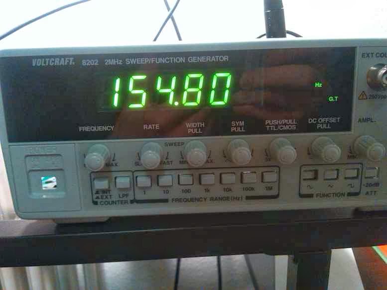
Fixing Voltcraft 8202 sweep/function generator
Recently I ordered from ebay a defected Voltcraft 8202 function generator. It powered up properly and showed on the display a frequency. It wasn't completely damaged but there was no output signal, no matter what amplitude and offset I set there was 0 Volts on the output.
 I assumed that the problem is somewhere in output stage, this sound like a typical damage for a signal generator which once had its output overloaded. After opening the generator up I traced signal backwards from output connector, circuit diagram of output AB-class amplifier area looks like this:

Multimeter set to a diode test showed that Q14 was damaged, additionally R59 and R60 were overheated, one of them was opened, another looked bad but was still conducting. R57 in the negative feedback has drifted because of overload and was around 30K instead of 6.8K. I replaced Q14 with BC557, put new R59, R60 and R57 but there still was no output signal.
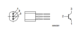
It took me a while to notice that the original 2N3906 has got different pinout than the BC557 which I used, actually pin numbers are the same: emitter is the pin number 1 but take a look at this screenshots from datasheets:
The order in which pins are numbered is different. After rotating the BC557 generator started to work again. I enjoyed watching sinusoidal and triangle signals on a screen of my oscilloscope. I didn't enjoyed watching square waves because their edges are really slow, slew rate of around 1V/us. It looks acceptable at 100kHz, but at 1MHz it is not a square wave anymore.
Another observation is about PCB quality, it was enough to solder one point twice to tear copper of the PCB:

I don't mind because not very often I look at this PCB but it says something about overall product quality.
This is actually really popular topology, signal (point A) is fed to the positive input of the differential amplifier built around Q12 and Q13, Q14 drives Q15 and Q16 push-pull output stage while D6 and D7 provides bias voltage for Q15 and Q16. Signal from the point between R59 and R60 is fed back to negative input of Q12 and Q13 amplifier - this negative feedback improves linearity. Between point B and the output BNC connector there is additional switchable 20dB voltage divider which I didn't show on the circuit.
Multimeter set to a diode test showed that Q14 was damaged, additionally R59 and R60 were overheated, one of them was opened, another looked bad but was still conducting. R57 in the negative feedback has drifted because of overload and was around 30K instead of 6.8K. I replaced Q14 with BC557, put new R59, R60 and R57 but there still was no output signal.
It took me a while to notice that the original 2N3906 has got different pinout than the BC557 which I used, actually pin numbers are the same: emitter is the pin number 1 but take a look at this screenshots from datasheets:
 |
| 2N3906 |
 |
| BC557 |
Another observation is about PCB quality, it was enough to solder one point twice to tear copper of the PCB:
I don't mind because not very often I look at this PCB but it says something about overall product quality.
Subscribe to:
Posts (Atom)